
info@snmhardware.com 008618965075392

As energy storage, power conversion, and industrial equipment continue to move toward higher power density, high-current connections are becoming increasingly important. Connectors must transfer substantial current within limited space while also accommodating manufacturing tolerances, vibration, temperature changes, and repeated mating. Much of this challenge is concentrated at the contact interface, where reliable electrical contact has to be maintained under these changing conditions.
Among the different contact solutions used in high-current connectors, the canted coil spring is unusual in one important respect: it can function both as a spring and as part of the contact system itself. Its inclined coils remain compliant under load and create distributed contact around the mating interface. In some connector designs, current also passes directly through the spring from one conductive component to another.
When mechanical contact and current transfer come together in such a small component, familiar spring parameters begin to carry additional meaning. Dimensions and load need to be understood in the installed condition; material selection may involve both spring performance and electrical requirements; and surface treatment can become part of the working contact interface rather than simply a finishing operation. These requirements ultimately come back to how the canted coil spring behaves in its actual application.
Why Contact Force Cannot Be Defined by One Number Alone
For many springs, specifying a load at a particular compressed position is a normal way to define performance. That remains important for a canted coil spring in a high-current connector, but once the spring is installed in a groove and engaged by a pin or another mating component, it has moved from its free state into its actual working condition. The force it produces now depends on its working deflection.
That working deflection is not necessarily identical from one assembly to another. The pin has dimensional tolerances, as do the groove and the spring itself. Even when every individual component meets its drawing requirements, their combined dimensional variation can result in slightly different installed spring positions. A specification such as Spring Load = X N therefore does not fully describe the functional condition of the spring.
A more useful approach is to establish the range of deflection the spring may actually experience:
Minimum Working Deflection → Nominal Working Deflection → Maximum Working Deflection
The spring’s force-deflection behavior can then be considered across this range. The question is no longer simply how much force the spring can produce, but whether it can maintain an appropriate contact force throughout the assembly conditions the connector may actually experience.
Contact force also needs to be balanced. Too little force can make the interface more sensitive to dimensional variation, vibration, and changes in surface condition. Increasing the force too far, however, can raise insertion and extraction forces and may contribute to greater mechanical wear at the contact surfaces. A high-current connector therefore does not necessarily need a spring that produces more force; it needs a spring that produces the right force within the right working range.
This is where canted coil geometry becomes particularly useful.
How Canted Coil Geometry Handles Working Deflection
The most recognizable feature of a canted coil spring is the inclination of its coils. Under load, these coils deflect and rotate according to their geometry, producing a force-deflection response that differs from that of a conventional compression spring. For an electrical contact, the important feature is not simply that the coils are inclined, but the useful working region created by this geometry.
Accommodating Displacement Without a Large Change in Force
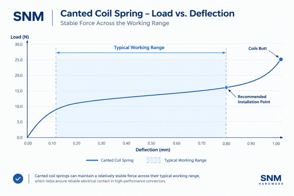
With appropriate geometry, a canted coil spring can provide a relatively flat portion of its force-deflection curve within its intended working range. This should not be interpreted as perfectly constant force. Force still changes as the spring deflects; the useful characteristic is that, within the appropriate region, a certain amount of displacement variation does not necessarily result in an equally large change in force.
That behavior becomes particularly relevant when connector tolerances are considered. Variations in the pin, groove, and spring dimensions ultimately create a range of installed deflections. If that range is properly positioned within a suitable portion of the spring’s force-deflection curve, contact force can remain within the required window even as the actual assembled position varies.
The canted coil spring does not eliminate tolerances. It changes how the contact system responds to them.
The practical relationship is therefore between the Connector Tolerance Window and the Spring Working Range. How well these two ranges are matched has a direct influence on the spring’s functional performance in the connector.
Distributed Contact Around the Circumference
Another characteristic of the canted coil spring is the large number of coils participating in the contact interface. This is often described simply as “multiple contact points,” but distributed contact is a more useful way to understand what is happening mechanically.
If the pin is slightly eccentric, or local mating conditions vary around the interface, coils at different positions can respond elastically to those local conditions while the spring continues to maintain contact around the assembly. This matters because a production connector does not operate with perfect CAD geometry; it operates with real components carrying manufacturing and assembly variation.
In some high-current connector designs, those same coils also participate directly in current transfer. The conductive path can then take the form:
Pin → Canted Coil Spring → Housing
At that point, the spring is no longer simply an elastic component applying pressure behind a separate contact. It becomes a functional part of the electrical contact path itself. Once the spring carries current, material selection has to be considered differently as well.
Material Selection When the Spring Also Carries Current
A canted coil spring must first perform as a spring. Elastic strength, fatigue behavior, stress relaxation, operating temperature, and environmental resistance therefore remain fundamental material considerations. For a spring that also participates directly in current transfer, however, the material must support both mechanical spring performance and electrical contact performance.
High conductivity alone does not make a material suitable for a canted coil spring. The material still has to maintain the required elastic behavior at the intended working deflection. Conversely, a material with excellent mechanical spring properties may require a different material or surface strategy when electrical performance becomes important.
This is why commercial canted coil electrical contacts use more than one material route. Beryllium copper, zirconium copper alloys, and stainless steels are established options for electrical contact springs. In broader canted coil spring applications, nickel-based alloys may also be used where temperature, corrosion resistance, or mechanical requirements justify them.
The material question is therefore not simply which material has the highest electrical conductivity. What matters is whether, after meeting the electrical requirement, the material can continue to perform properly as a spring under its actual working conditions. For a component carrying both mechanical and electrical functions, neither side of that requirement can be ignored.
Why Plating Is More Than a Final Surface Treatment
When current passes directly through a canted coil spring, the wire surface is no longer just the outside of the spring; it is part of the working contact surface. Commercial canted coil electrical contacts use surface systems including gold, silver, nickel, and tin, depending on the application. Silver-plated copper-alloy springs, for example, are an established option where high electrical conductivity is important.
Plating selection, however, cannot be reduced to a ranking of electrical conductivity. Once the connector is mated, the spring surface is under contact pressure, and relative movement may occur during insertion and removal. Over repeated cycles, wear, corrosion, and interaction with the mating surface all become relevant.
The surface system therefore needs to be considered in terms of electrical conductivity, wear resistance, corrosion resistance, mating-material compatibility, and service environment. Plating thickness is similarly application-dependent; without knowing the actual contact conditions, there is little value in assigning a universal thickness to a canted coil electrical contact.
For this reason, the base material and plating are better treated as a functional material system rather than two unrelated specifications. The base material has to make the component work as a spring; the surface has to make it work as a contact. The finished part has to do both.
Closing the Canted Coil Spring Ring: Welding Considerations
Cant angle, coil geometry, pitch, and circumferential consistency all influence how a canted coil spring behaves. These manufacturing factors are discussed in more detail in our canted coil spring manufacturing and consistency guide.
For a closed-ring contact spring, however, there is another small area worth examining: the point where the two ends meet. After the spring has been formed to length, the ends need to be joined to create the finished ring. Welding is an established method for producing closed canted coil spring rings, and laser welding is one option for precision joining of fine spring wire.
The joint needs to be mechanically secure, but this alone does not define a good joint. On either side of the weld is a sequence of coils formed to a controlled geometry. Once the ends are joined, the welded region becomes part of that same spring.

End Alignment
The ends need to meet in the intended position. Poor alignment can introduce a local step or disturb the adjacent coils even if the weld itself remains mechanically sound. For a spring that relies on many coils working around a distributed contact interface, the joint should not create an unnecessary geometric discontinuity.
Local Heat Input
Canted coil springs are often produced from relatively fine wire, leaving a very small joining area. The welding process therefore needs to create a reliable joint while limiting unnecessary effects on adjacent coil geometry and the local material condition.
Laser welding can be useful for precision joining because its energy can be concentrated in a relatively small area. The final result, however, still depends on the material, wire diameter, end preparation, alignment, and welding parameters.
Condition After Welding
When the spring also carries current, the welded region remains part of the conductive component. Its final geometry and surface condition therefore need to remain compatible with subsequent surface treatment and the intended contact function.
The weld may occupy only a very small part of the ring, but it should not become an exception to the spring’s geometric and functional continuity. The objective is to close the ring reliably while preserving, as far as practical, the behavior established by the rest of the spring.
What Should Be Defined Before the Spring Geometry?
For a canted coil spring used in a high-current connector, parameters such as wire diameter, coil height, coil width, pitch, and cant angle will all need to be defined. But they should not necessarily be the starting point. Before those dimensions are established, the application needs to define what the spring is expected to achieve.
Step 1 — Define the Spring’s Function
The first question is whether the spring provides mechanical contact force only or also forms part of the conductive path. If current passes directly through the spring, mechanical, material, and surface requirements need to be considered together from the beginning.
Step 2 — Define the Installed Condition
Groove dimensions, mating-component dimensions, available space, and assembly arrangement determine where the spring will actually operate. The essential question is how much the spring will deflect after installation.
Step 3 — Establish the Working-Deflection Window
Nominal dimensions provide only one operating position. Relevant dimensional tolerances should also be considered to establish the expected:
Minimum / Nominal / Maximum Working Deflection
This is the displacement range the spring actually needs to accommodate.
Step 4 — Define the Required Force Across That Range
Once the working-deflection window is known, the corresponding contact-force requirement can be established. Instead of one isolated load value, the functional target becomes:
Working-Deflection Window × Required-Force Range
Together, these provide important engineering inputs for the spring geometry.
Step 5 — Translate Function into Spring Geometry
Only at this stage do parameters such as wire diameter, coil height, coil width, pitch, cant angle, and overall dimensions gain their full context. These parameters interact to create the required force-deflection behavior within the available installation space.
Simply copying the wire diameter or dimensions from another canted coil spring therefore has limited engineering value. What needs to be reproduced is not an isolated parameter, but the correct functional relationship.
Material and surface treatment then need to be matched with the current, temperature, mating materials, environment, and service conditions. The same logic continues into manufacturing: characteristics that strongly influence working deflection or force-deflection behavior naturally deserve greater process attention, while material condition, surface treatment, and the closed-ring joint need to be controlled according to their influence on final function.
Design establishes which characteristics control function; manufacturing has to keep those relationships from drifting during production.
Conclusion
What makes a canted coil spring useful in a high-current connector is not simply the fact that its coils are inclined. Its value comes from several functions working together: providing controlled contact force within limited space, accommodating a practical range of assembly variation, creating distributed contact through multiple coils, and, in some designs, carrying current directly through the spring itself.
These functions connect spring geometry, working deflection, material, plating, and manufacturing into the same engineering problem. A useful way to approach the application is therefore:
Application Requirements → Installed Condition → Working Deflection → Contact Force → Material & Surface → Spring Geometry → Manufacturing Control
The final drawing will still contain familiar specifications such as wire diameter, dimensions, tolerances, material, and surface treatment, but their real meaning does not exist only on the drawing. For a canted coil spring in a high-current connector, the final question is what those parameters allow the spring to do after it is actually installed.


